Thickener - NFT Series
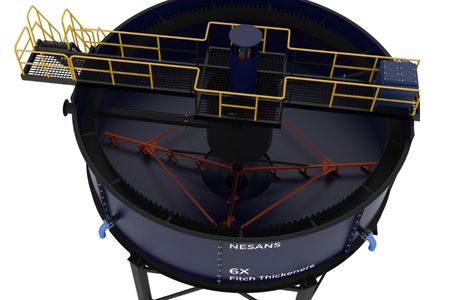
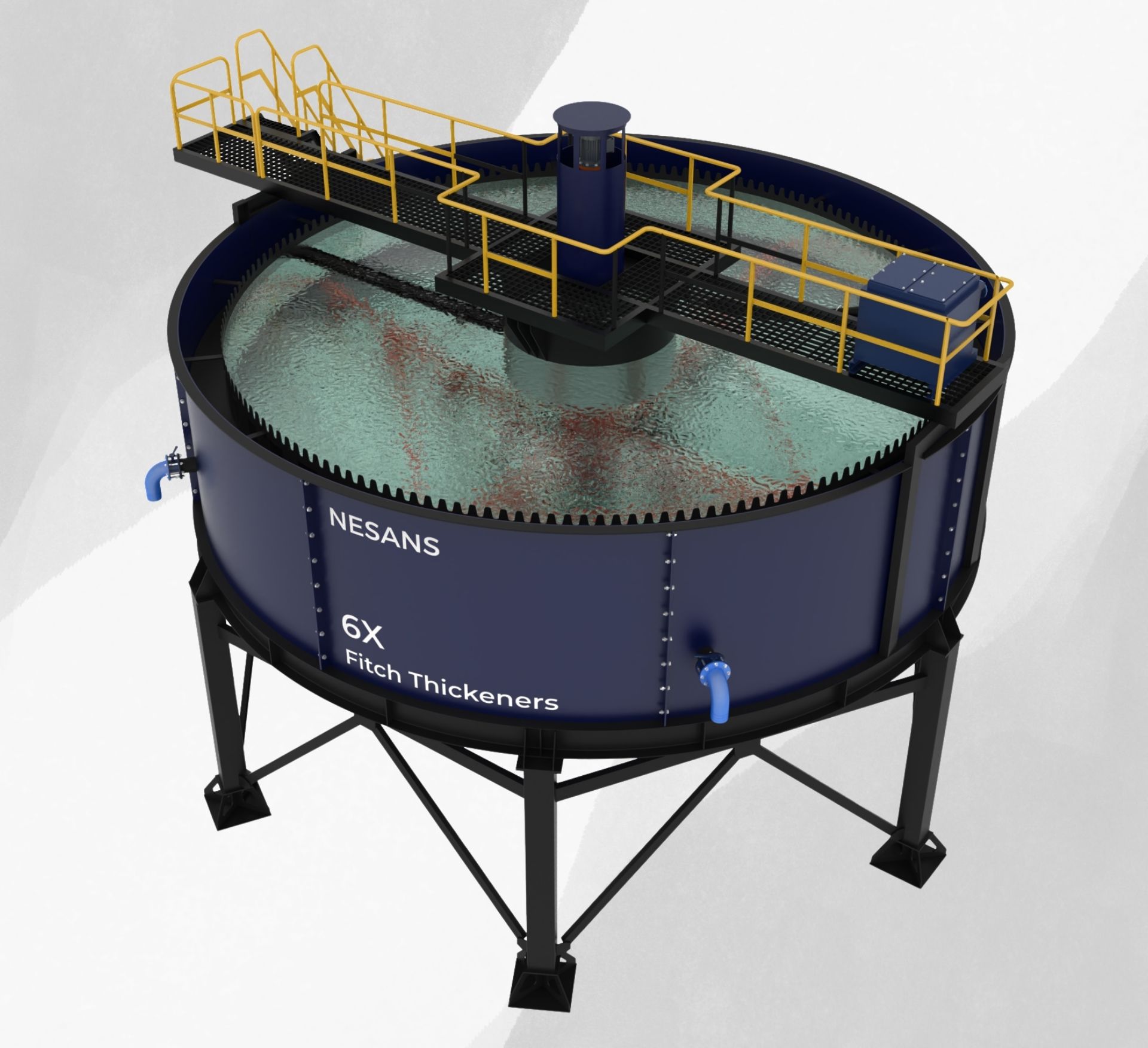
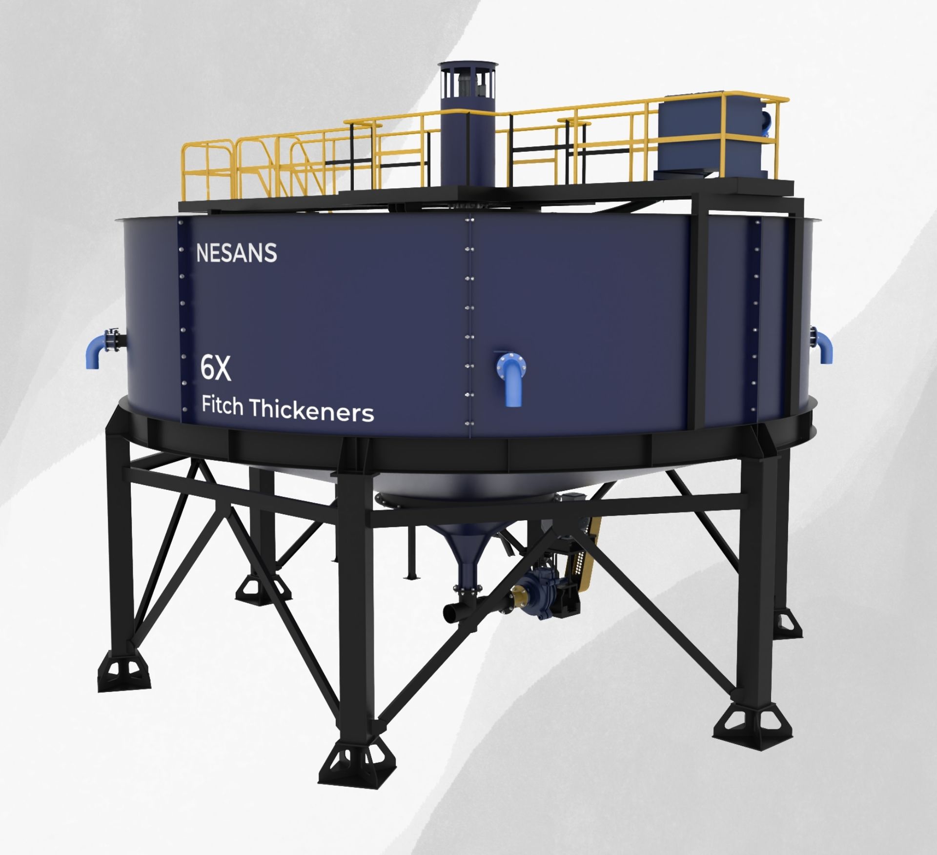
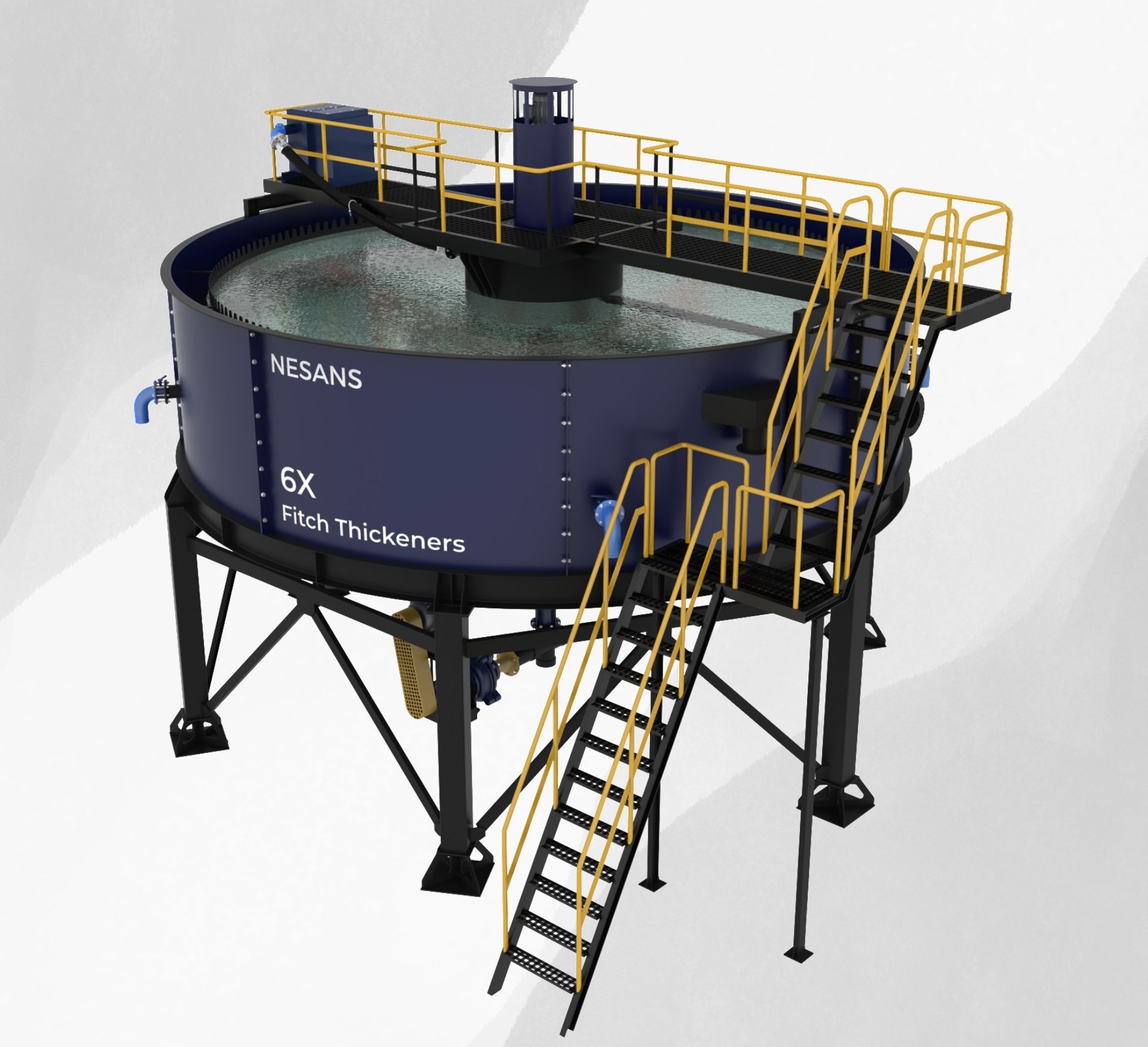
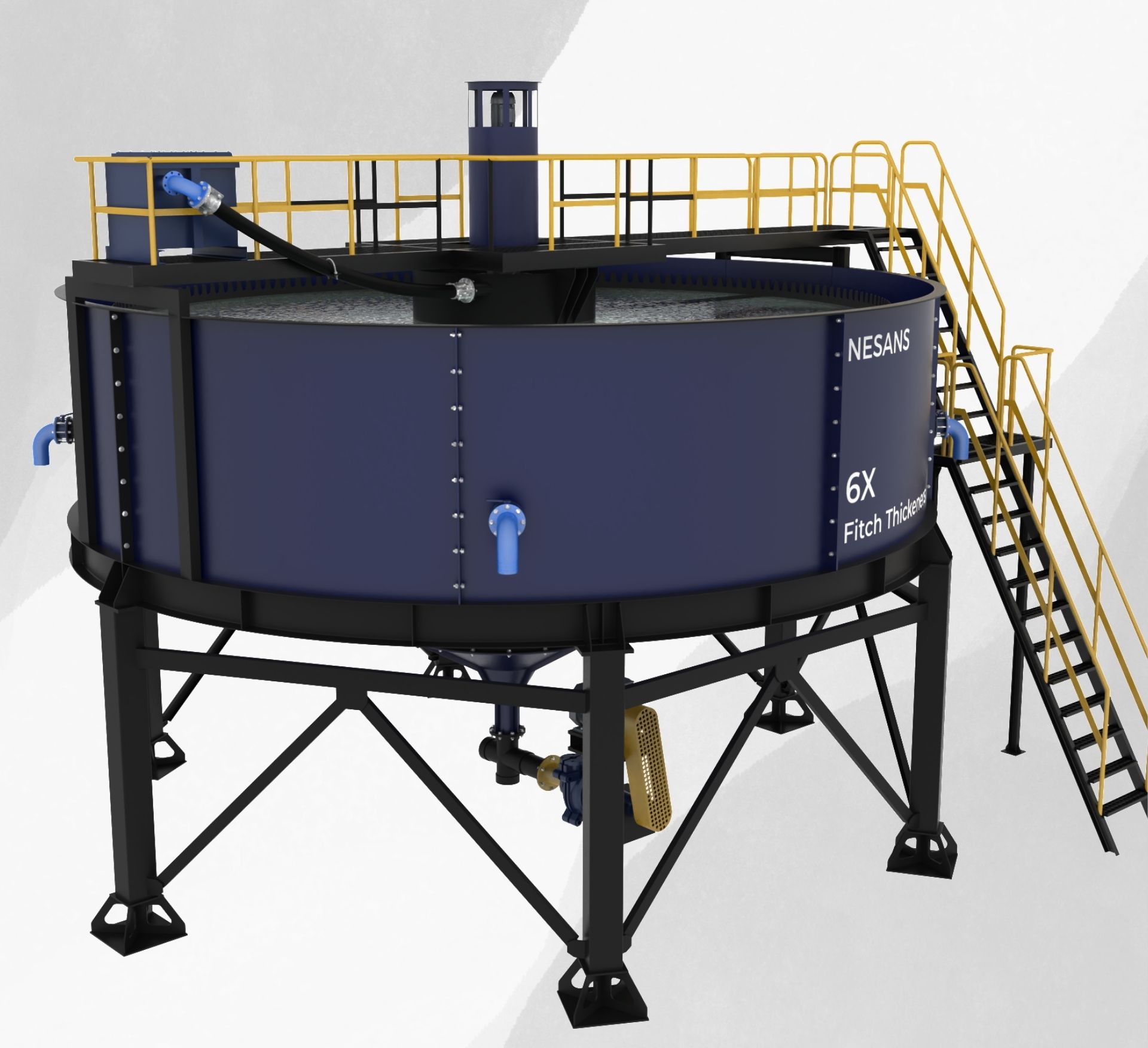
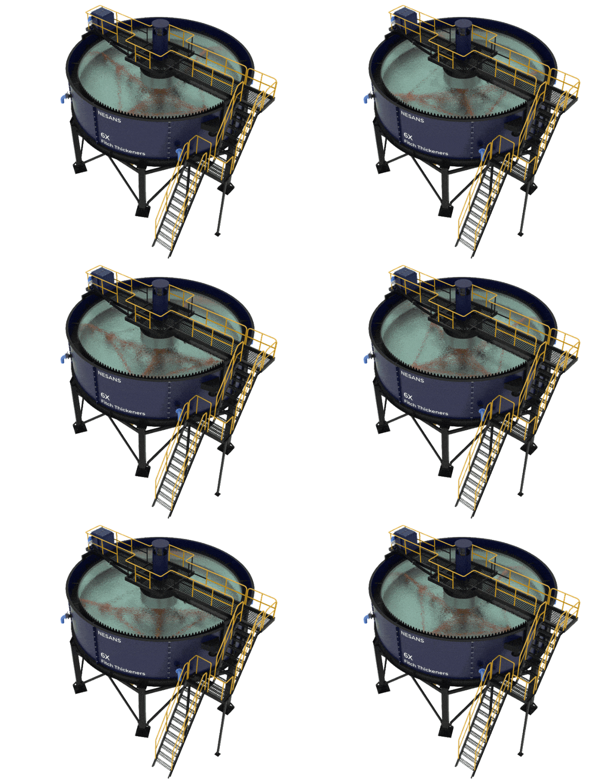
The Nesans NFT Series Thickeners are engineered for high-efficiency solid-liquid separation, making them an essential component in modern wet processing circuits. Designed to handle a wide range of slurry consistencies, these thickeners accelerate the sedimentation process, allowing for the rapid settling of solids and the recovery of clear process water. Their compact footprint and large settling area ensure optimal performance in industries such as sand washing, mineral beneficiation, and construction waste recycling.
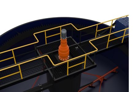
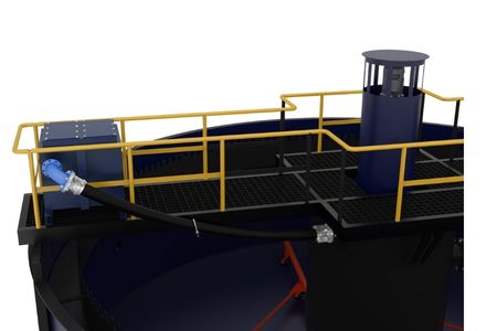
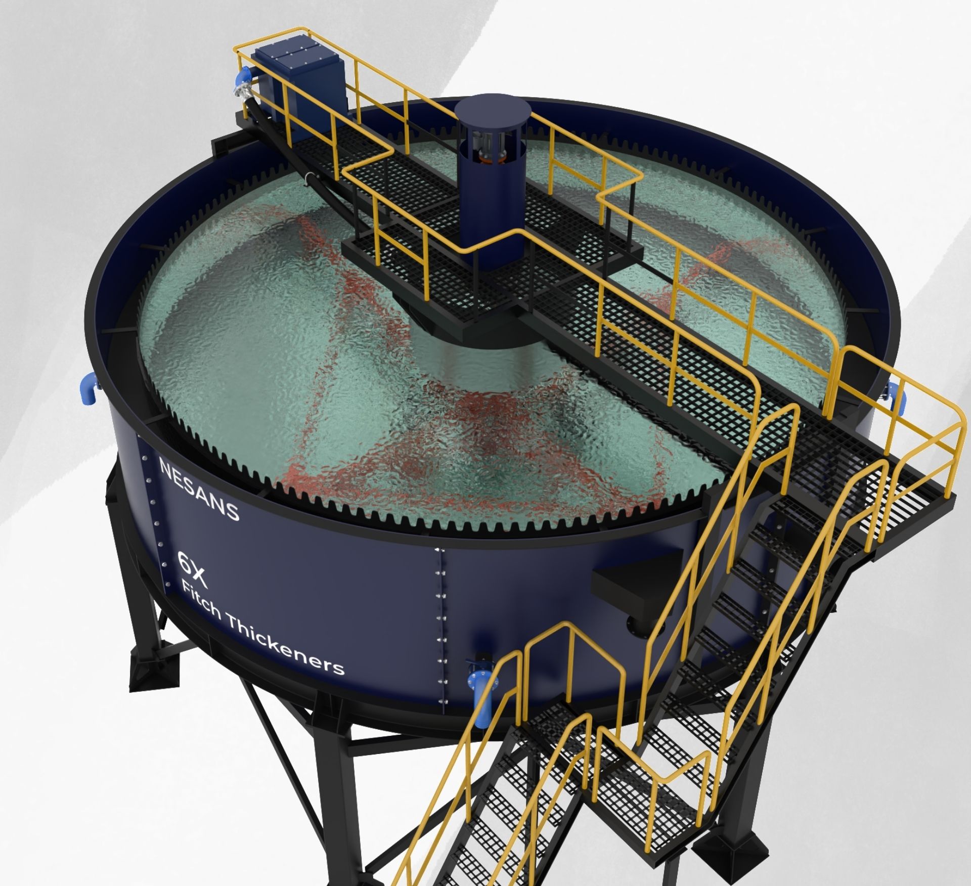
At the heart of the NFT Series is a robust rake mechanism that continuously stirs and compacts the settled sludge toward the underflow discharge. This ensures consistent dewatering performance, even with variable feed conditions. The carefully designed feedwell promotes efficient flocculation and even distribution of incoming slurry, reducing turbulence and enhancing clarity in the overflow water. These design optimizations contribute to faster thickening rates and lower chemical consumption.
Whether used as a standalone water recovery system or integrated into a closed-loop plant setup, the Nesans NFT Series helps operators minimize freshwater usage, reduce slurry disposal volumes, and meet environmental compliance.
Applications:
How It Works
The Nesans NFT Series Thickeners operate on the principle of gravity-assisted sedimentation, where solids in slurry are allowed to settle at the bottom of a large, open tank while clarified water overflows from the top. Slurry enters through a centrally located feedwell that slows down the velocity of incoming material, promoting uniform distribution and effective flocculation. This controlled flow minimizes turbulence and enhances the settling of fine particles.
As solids begin to settle, a slow-rotating rake mechanism moves continuously across the tank floor, gently pushing the concentrated sludge toward the central underflow discharge cone. This mechanical action prevents the buildup of solids, ensures even compaction, and improves the consistency of the discharged underflow.
Meanwhile, the clear supernatant liquid rises to the top and is collected through overflow launders positioned around the tank’s perimeter. This clarified water is then reused in the processing circuit, significantly reducing the plant’s freshwater requirement. The NFT Series is designed to handle varying slurry loads and densities, making it a reliable solution for efficient water recovery and solid concentration in a wide range of applications.
Features and Advantages
Specifications
| Model No. | Thickener Diameter (m) | Thickener Height (m) | Underflow Rate (TPH) | Slurry Loading Rate (m³/hr) | Input % Solids (%) | Underflow % Solids (%) | Total Power Required (kw) |
|---|---|---|---|---|---|---|---|
| NFT-6X | 6 | 2 | 12 | 72 | <15% | 25-35% | 30 |
| NFT-10X | 10 | 3 | 30 | 180 | <15% | 25-35% | 40 |
| NFT-12X | 12 | 4 | 40 | 250 | <15% | 25-35% | 55 |
| NFT-15X | 15 | 5 | 50 | 300 | <15% | 25-35% | 60 |
| Model No. | Thickener Diameter (ft) | Thickener Height (ft) | Underflow Rate (STPH) | Slurry Loading Rate (gpm) | Input % Solids (%) | Underflow % Solids (%) | Total Power Required (hp) |
|---|---|---|---|---|---|---|---|
| NFT-6X | 20 | 6.5 | 13 | 317 | <15% | 25-35% | 40 |
| NFT-10X | 33 | 10 | 33 | 792 | <15% | 25-35% | 54 |
| NFT-12X | 39 | 13 | 44 | 1100 | <15% | 25-35% | 74 |
| NFT-15X | 49 | 16 | 55 | 1320 | <15% | 25-35% | 80 |
Product Gallery
Relevant Products
Contact Us
Want to Know More? Need a Quote? Please Complete the form below and our Sales Engineer will follow up shortly.

