






A crushing plant is a chain of machines that each like a steady diet, fed by a world that delivers in lumps — a truck dumps, a primary surges, a stage trips. The surge bin is the shock absorber between them: a buffer that lets an upstream swing pass without starving or flooding what comes next. Size it wrong and the whole plant stutters.
This article explains what a surge bin buffers, how to size its live capacity for a target ride-through time, and the trade-off between a bigger buffer and the cost and space it takes.
What the bin buffers
A surge bin decouples the rate into it from the rate out of it. When the feed exceeds the draw, the bin fills; when the feed falters, the bin keeps the downstream fed from its stored contents. The useful measure is the live capacity — the working volume between the high and low control levels — expressed as the time it can sustain the draw:
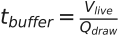
where  is the live tonnage and
 the downstream demand rate.
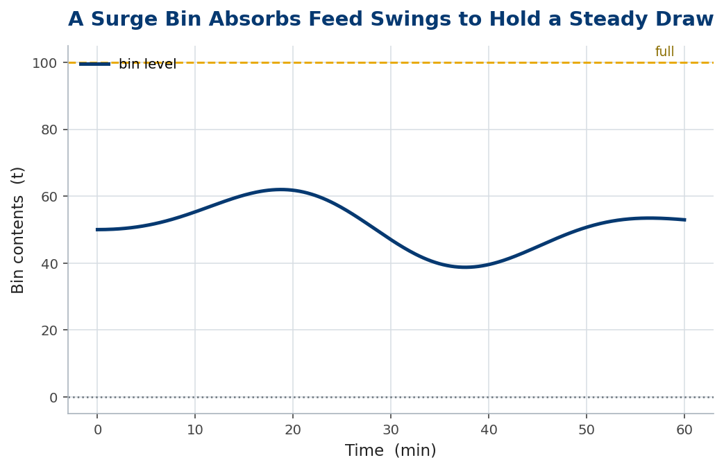
Worked example 1 — sizing for ride-through
A secondary draws 300 t/h, and the primary it feeds from stops for 12 minutes during a routine liner check or a blocked chute clear-out. To keep the secondary running through that gap, the live capacity must be

A 60-tonne live bin lets the secondary ride through a typical primary interruption without stopping — and a plant that does not stop and restart its downstream stages on every blip runs far more tonnes per shift.
The trade-off: how much buffer
More buffer is more resilience, but at rising cost. A bigger bin or stockpile costs capital and space, and beyond a point the extra ride-through earns little — it guards against ever-rarer events. The buffer time scales linearly with live capacity, so you can read off exactly how many minutes each extra tonne of bin buys.
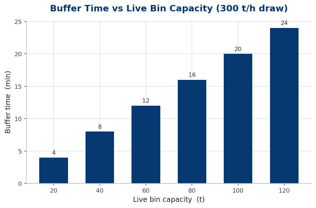
Worked example 2 — matching buffer to the disturbance
The right size depends on what you are buffering. A bin smoothing the lumpiness of truck dumps onto a primary needs only a few minutes of capacity — enough to average several dumps. A bin protecting a washing plant from a primary trip needs 10–15 minutes, the typical clear-and-restart time. A bin feeding a continuous kiln or a loadout that must never stop might need an hour. Size the buffer to the duration of the disturbance it exists to absorb — not to a round number.
| Buffers against | Typical ride-through | Implication |
|---|---|---|
| Truck-dump lumpiness | 2-5 min | small bin / hopper |
| Upstream stage trip | 10-15 min | mid surge bin |
| Loadout / kiln continuity | 30-60 min | large bin / stockpile |
| Shift-scale buffering | hours | live stockpile |
In practice
Place the surge buffer where the plant is most rhythm-sensitive — ahead of a washing plant or a continuous loadout that suffers most from stop-start. Size the live capacity to the duration of the disturbance you are absorbing, and instrument the bin with level control so feeders modulate to keep it in its working band, neither overflowing nor running empty. Mind the material: a surge bin must draw down reliably without bridging or ratholing, so design the outlet and draw-down for the stickiest, wettest material it will hold — a buffer that hangs up is worse than no buffer at all.
Common mistakes
- Sizing to a round number. Size the live capacity to the duration of the disturbance it absorbs, not ‘100 tonnes’.
- Confusing total with live capacity. Only the volume between control levels buffers; dead capacity does nothing.
- Ignoring draw-down behaviour. A bin that bridges or ratholes starves the plant — design the outlet for the worst material.
Flow pattern and outlet sizing: the bin that must not arch
A surge bin only buffers if it actually discharges, and the commonest way a bin fails is not structural but flow: the material arches over the outlet or forms a stable rathole, and the ‘buffer’ hangs up just when the plant draws on it. Two flow patterns are possible, and the difference decides reliability. In funnel flow, material moves only in a central channel while the rest stands dead; in mass flow, the whole contents move together toward the outlet.
Mass flow is what a surge bin wants. It uses the full live capacity (no dead regions stealing buffer volume), it is first-in-first-out (no stagnant material going stale or segregating), and it resists ratholing. Achieving it requires steep, smooth hopper walls and, critically, an outlet large enough that the material cannot form a stable arch across it. The minimum outlet size depends on the material’s cohesive strength — sticky, fine, wet material needs a much larger outlet than free-flowing rock.
The design inputs come from flow testing the actual material: its wall friction against the proposed liner, and its cohesive (arching) strength when consolidated under the bin’s own head. From these, established hopper-design methods give the hopper angle for mass flow and the critical outlet dimension that prevents arching. Skipping this and sizing the outlet by eye is why so many bins designed for ample volume still bridge and starve the plant.
So size a surge bin in two parts: the live capacity for the ride-through time, and the outlet and hopper for reliable mass flow of the worst (wettest, stickiest) material it will hold. A bin that is big enough but flows in a funnel wastes most of its capacity and risks hanging up entirely — a buffer that cannot be drawn on is no buffer at all.
The bottom line
A surge bin decouples feed from draw, riding through upstream swings for  . Size the live capacity to the duration of the interruption you must absorb, and place it where the plant is most rhythm-sensitive.
Match the buffer to the disturbance, control the level so feeders modulate, and design the outlet for reliable draw-down — and the plant stops stuttering on every dump and trip, turning ride-through into tonnes.
Frequently asked questions
How do I size a surge bin?
Live capacity = draw rate x ride-through time. Decide how long the bin must sustain the downstream during an upstream interruption, then multiply by the draw rate.
What is live versus total capacity?
Live capacity is the working tonnage between the high and low control levels — the part that actually buffers. Dead volume below the outlet does not count.
Where should a surge bin go?
Where the plant is most sensitive to stop-start — typically ahead of a washing plant or a continuous loadout.
Key takeaways
- — live capacity over draw rate.
- Size the buffer to the duration of the disturbance it absorbs, not a round number.
- Only the live volume between control levels buffers; dead capacity does nothing.
- Design the outlet for reliable draw-down — a bridging bin is worse than none.
